Ryan Schulok
Mechanical Option
Pharm Corporation
-Pills, DE-

GENERAL BUILDING DATA
Building Name | Pharm (fictitious name)
Locations | Pills, DE (fictitious location)
Building Occupant Name | confidential
Occupancy/Function Type | Office Building
Size | 154,000 SF
Stories above grade | 4 stories
Total Floors | 4 stories
Dates of Construction (start – finish) | May 25, 2015 – Oct. 03, 2017
Project Delivery Method | Design – Bid – Build
Actual Cost Information | $90 Million – including both Core & Shell and Interior Fit-out
Pharm decided to divide this project into two main phases: Core & Shell and Interior Fit-out. Through the bidding process, certain teams were able to solidify both phases of work, while others, like the architect, differ between Core & Shell and Interior Fit-out. Below are the teams of each phase. An image of the Interior Fit-out atrium, from Granum A/I, is in Image 2, below.
Owner
CM
Architect
Structural Engineer
MEP/FP Engineer
Interior Designer
Acoustical Consultant
Landscape Architect
Civil Engineer
Green Roof Consultant
Lighting Designer
CORE & SHELL
confidential
The Whiting Turner Company
Granum A/I
A.W. Lookup Corporation
AKF Group
n/a
Metropolitan
Andropogon Associates
Duffield Associates
n/a
The Lighting Practice
INTERIOR FIT-OUT
confidential
The Whiting Turner Company
Mitchell Associates
A.W. Lookup Corporation
AKF Group
Mitchell Associates
Metropolitan
n/a
n/a
Roofmeadow
The Lighting Practice

ARCHITECTURE
2.1 Design and Functional Components
Functionally, this building consists of two separate structures that are used together as one. The left structure is a 475-car parking garage that is connected to the main building, a 154,000 square feet office building that acts as the Headquarters for Pharm Corporation. Upon walking into this building, one will encounter a large 43,500 SF floor plan, with a main lobby area, building services, loading docks and some office space located on the East side.
Continuing up the floors, each one is reduced in square footage due to the offset created by the atrium from the center staircase in the lobby, shown in Image 3. The second floor houses mostly office and conference room space. Moving onto the third floor, the kitchen and dining locations were constructed, with the dining space having a two-floor, 30’-0” ceiling to give the space a sense of large volume, welcoming all individuals to take a break from work to enjoy their lunch. This space can fit up to 700 people for a meeting space for outside events. This space is completely walled with curtain walls, and contains a saw-tooth ceiling, depicted in Image 4. The saw-tooth allows for natural light to flood the space from the ceiling down to the floor.
Breaking this building into simple building blocks, there are few spaces that Granum A/I wanted to emphasis. Image 5 shows these visually. The first level they wanted a large, 4-story atrium space to welcome its employees and clients. Providing as a large circulation point, the individual can either travel down a double height corridor space that has a curtain wall assembly for the entire length. If the individual traveled up the glass-railing staircase, they would be brought to the second floor, and then to the third. This is offset from the first-floor corridor space, giving it another circulation path back to the dining area. With two sides covered in curtain walls, this provides clients and employees with an abundance of natural light to allow them to enjoy their lunch break.
Image 2 - Interior Image provided by Granum A/I


Image 3 - Grand Staircase
Image 4 - Sawtooth Ceiling
Image 5 - Conceptual Building Block
2.2 Major Model Codes
Major National Model Codes | American with Disabilities Act 2010 (ADA)
American Institute of Steel Construction (AISC)
American National Standards Institute (ANSI)
International Building Code 2015 (IBC)
International Energy Conservation Code 2012 (IECC)
International Fuel Gas Code 2015
International Mechanical Code 2015 (IMC)
International Plumbing Code 2015 (IPC)
Leadership in Energy and Environmental Design 2009 (LEED)
National Fire Protection Association (NFPA)
National Electrical Code (NEC)
2.3 Zoning
Zoning Requirements for Pills, DE has certain requirements for Group B – Business. According to
section 18.30.050 under C-2 Zoning, the property development standards are:
Minimum lot area | 70,500 SF
Minimum Length by Width | 50 ft x 150 ft
Floor-to-Area Ratio | Not exceed 0.5 FAR
Building Height within 100 ft of R-1, R-2 | 65 ft
Building Height within 100 ft of R-3 | 45 ft
2.4 Historical Status
Although this location in Delaware has many historical sites and streets, the location of Pharm Corporation is not within the historical zoning boundaries. Therefore, no historical accommodations have to be met.
3.1 Curtain Wall System
There are three distinct ways that this structure used curtain wall systems: A) completely vertical glass, B) East façade containing a full-height lean in curtain wall, and C) West façade containing a full-height lean out curtain wall. The image on the left, image 6, depicts both the curtain wall systems A and B, while image 7 on the right shows the outward slanting glass for system C. The two materials used are glass assembly (AGA) and metal panel wall assembly (MPWA). MPWA is illustrated in closer detail in 3.4 Exterior Wall Construction. The leaning in of the East curtain wall system allows the natural light of the sunrise to enter the space, while the outward leaning of the west side protects the individuals in offices from the late afternoon direct sunlight. This is how all the natural light gets into the building since there are no punch-out style windows.
BUILDING ENCLOSURES

Image 6 - Curtain Wall Systems A & B Image 7 - Curtain Wall System C
3.2 Roofing
Roofing structures were designed based on the location of where the assembly is located. As were the curtain walls, there are three different roofing assemblies that are being used throughout this building.
Membrane Roof Assembly 1 | This membrane is located on almost the entire roof, except for the knuckle of the building. The structure does not have to be as stiff, since there are no units being placed on this roof, shown below.
Membrane Roof Assembly 2 | The knuckle membrane has composite roof decking to support the rooftop units. The metal deck could not support these units, so the increased strength of the concrete can disperse the load.
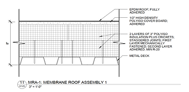

Image 8 - Membrane Assembly 1 Image 9 - Membrane Assembly 2
Roof Terrace Assembly | The roof terrace area of the roof, which are located on the the set-backs from the floors, and also located all over the roof of the garage. To support the weight of the vegetation, there is a terrace slab on metal roof decking. On top of the slab is insulation layers between the vegetation media and the terrace slab, and then separated by waterproofing so the terrace slab is dry. On top of the root barrier is the vegetation media, which a detail can be found in Image 14. This detail for the roof terrace assembly is in Image 10.
3.3 Garage-to-Building Connection
Although this garage that Pharm Corporation owns is not part of this building investigation, the connection between these two different entities is important. Having a seamless transition form the parking garage to the building is important for circulation flow. Taking advantage of the drastic slope on this site, the garage is recessed down into the ground on the slope. This allows the top tier of the garage to be flush with the first floor of the office headquarters building. This allows clients to take an elevator or stairs to the top of the garage and enter into the grand atrium lobby. Located below is an enlarge axonometric view of the building and garage’s seamless connection.
3.4 Exterior Wall Construction
The exterior walls for Pharm consist of the curtain wall systems, as discussed above, along with metal panel wall assembly. Image 12, to the right, shows the wall assembly of the metal panel wall. Located at the top of the next page, image 13, is an elevation view showing these two predominant material systems. Clear represents glass curtain wall, while the grey areas are the metal panels.

Image 10 - Roof Terrace Assembly

Image 11 - Axonometric of Garage-t0-Building Connection
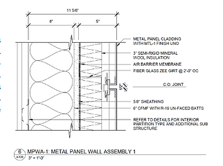
Image 12 - Metal Wall Assembly
SUSTAINABILITY
Sustainable strategies used within this building are as follows: Mechanical | Air-side economizer, capable of 22,000 CFM to 25,000 CFM, dependent on allocation of the unit, with minimum outdoor air of 4,400 CFM Unit refrigerant charge shall comply to the LEED Criteria for refrigerant impact of less than 100 ton of capacity
Electrical | All spaces, per occupancy, abide ASHRAE 90.1 and LEED requirements for lighting power
Green Roof | A green roof was installed on both the office space and garage space. A description of this system is below.
The green roof for the main office building has three main areas; areas with companion pavers for individuals to sit with outdoor furniture, areas with vegetation in a 4” media, and areas with vegetation and an 8” media. A green roof profile is located in Image 14, showing the breakdown of the layers on top of the roof assembly. As the surface growth media (S. G. Media) increases in thickness, the foundation growth media (F. G. Media) increases also, generally being approximately 1/3 the thickness of the surface growing media.
If the area of the roof contains concrete pavers, it follows a different roof structure above the roof assembly for the building. Image 15 illustrated the changes between having green vegetation and having concrete pavers. The main difference would be the high strength geotextile that holds up the setting bed for the pavers.
The reason that a green roof is a sustainable choice is because the benefits are providing to both the building environment and the outdoor environment. The green roof collects the water, reducing water run-off of the building. There is a reduction in the heat island effect, which reduces greenhouse gases being emitted into the atmosphere. Surrounding atmosphere will have improved air quality from the vegetation emitting oxygen and absorbing CO2 molecules.
On the energy side, the green roof will maintain a more manageable temperature when it comes to heating and cooling the space. The vegetation will remain cooler than the summer air and warmer than the winter air, offsetting both the heating and cooling load within the space, at least for the floors with green roof above them. Not only does the vegetation absorb the water to maintain temperatures, the vegetation absorbs sounds that may be protruding from surrounding areas. This reducing the need for higher ceiling impact isolation class (IIC) levels.
Primary Engineering Systems
1.1 Structural
Supporting the two 270-ton cooling towers outside of the building is a 5” slab on grade, with 6X6 W2.1XW2.1 welded wire frame on an 8” granular base, with shrinkage joints at 15’-0” on center. This slab type continues into the central core of the building. Each wing of the building, East and West, are set on 4” slab on grade with #5/CY fiber reinforcement on 4” granular base provide shrinkage joints every 15’-0”. In locations that have high density fill areas, 5” slab on grade with welded wire frame is used.
Around the stairs are steel framing. Steel beams of W24X103 are connected to the stair framing by W12X14 beams. Load is transferred to the column of W14X211, and dispersed by the column footings. All column footings are cast-in-place concrete with their footings ranging from 4’0” square to 8’-0” by 10’-0”. Most of the interior beams are W21X44 in a 40’-0” by 30’-0” typical bay, with W16X26 beams being on the north perimeter in a 30’-0” by 30’-0” bay. Beam reactions for the interior beams are 35 Kips, while perimeter beams are 25 Kips. These beams support a 6-¼” lightweight concrete slab on 3” X 20 GA galvanized composite deck. This is consistent throughout all the floors. Roof construction of 26K9 beams in the 40’-0” by 30’-0” bay are connected to 22K4 Vulcraft beams in the 30’-0” by 30’-0” bay, which support a 1-½” X 20 GA galvanized metal roof deck. This supports the roof load and roof terrace assemblies throughout the building.
1.2 Construction
The Whiting-Turner company was both the general contractor and construction manager in this design-bid-build project. Pharm Corp. of 150,000 SF costs a total of $93,000,000, costing $620/SF. The construction schedule is May 25, 2015 – Oct. 03, 2017, totaling 29 months.
This building was phased into three stages: 1) Core and Shell, 2) Interior Fit-out, and 3) Attached parking garage. They are all completed by Whiting-Turner, but designed by different architects. The main building is constructed on a flat slab, while the parking garage is excavated out of the sloping ground. Excavating the ground for the parking garage made the top floor of the parking garage level with the ground floor of the main building. This allows circulation between the parking garage and the office building.
1.3 Electrical
A utility-owned pad-mount transformer located directly outside the building with a 2500A secondary service at 480Y/277, 3-phase, 4-wire provides power throughout the building, along with 24 panelboards connected to all electrical demands. Both the transformer and panelboards are connected directly into a main switchboard (MSB).
A generator provides standby power and distributes it to all electric closets. A 30 kVA step-down transformer and corresponding 100A, 208/120V panelboard are located on the 1st and 3rd floors. All of the fans, pumps and electrical equipment are fed from combination motor starters located in electric closets or mechanical rooms. The kitchen has 4 panelboards for all of the equipment within.
1.4 Lighting
Utilization of natural light due to the large curtain wall systems throughout the building façade is the main source of lighting for the open-concept office space. Controlling of natural light entering the space is done by angling the East-facing class inward, while leaning the West-facing glass outward. This strategy allows light and heat to enter in the morning, while rejecting direct light in the evenings. Vacancy or occupancy sensors are used within office, conference and workroom, storage rooms, and lavatories to conserve lighting energy.
State-of-the-art daylight responsive dimming controls are used within the atrium and dining areas. Atrium areas use LED downlight to illuminate the space, while the dining area uses both LED wallwasher lights and LED downlights. Lighting on the roof for terrace areas provides emergency lighting on all railing areas for safety precautions.
1.5 Mechanical
The cooling demand for Pharm Corp. is served by two 270-ton closed circuit, evaporative cooling towers, creating condensate water for water-cooled DX air-handling units. Condensate pumps are used, rated at 810 GPM, with variable frequency drives to adjust the mass flow rate of condensate entering the AHU. For the heating side, interior spaces are heated by electric reheat coils located in the variable air volume (VAV) units. Perimeter spaces utilize both electric reheat coils along with electric perimeter baseboard, located below curtain wall glass systems. A smoke exhaust system is used within the atrium to remove 180,000 CFM in case of a fire, supplemented by 120,000 CFM of make-up air. This negative pressure area constricts fire smoke to be removed without being exposed to office areas.
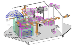
As for the air-side equipment, two mechanical rooms per floor each house one air-handling unit. One mechanical room serves both the West side and central core, while the other unit serves the East side. Offsetting the cooling and heating demand within the building, an air-side economizer with enthalpy based control is utilized when ambient temperatures permit. Carbon dioxide monitors are implemented in conference rooms to increase outdoor air ventilation as needed. Serving internal conference rooms are individual rooftop units, accommodated with an air-side economizer with the removed air from the space.
Additional Engineering and Support Systems
2.1 Fire Protection
All means of fire protection are in compliance with NFPA and IBC, with fire alarms and smoke detectors throughout each floor. A class 1 standpipe system is used within the building, which is a 4” standpipe riser located within each mechanical shaft. Sprinklers on the floor are provided water from these standpipes. Fire dampers are located in any full-height wall penetrations of 2-hour fire-rated wall and in transfer ducts moving air from the plenum to the return air fans.
2.2 Transportation
There are three elevators and four stairwells within the building. Two elevators are for general use, while one is a freight elevator for the dining and kitchen on the 3rd floor. A grand 4-story, glass railing staircase is within the main atrium of the building. This is the central point within the building. Located adjacent to the main office building is a parking garage. Transportation to the building for the employees can park within this parking garage, and enter the first floor of the atrium from the fourth floor of the parking garage.
2.3 Telecommunications
A passive infrastructure cabling system was designed to provide a pathway for telephony, Ethernet and other communication systems used day to day within the facilities. The new building communications are to also be connected to the existing building on site, owned by Pharm Corp. The connection of services is by underground duct banks each consisting of two 5” schedule 40 PVC encased on a concrete envelope. These duct banks terminate in the main distribution frame (MDF) room of each building.

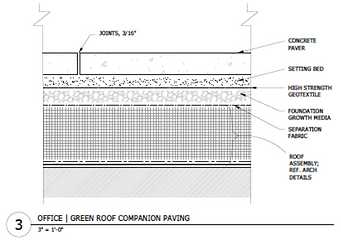

Image 13 -Southeast Building Elevation
Image 14 -Vegetation Media Construction Detail
Image 15 -Roof Concrete Paver Construction Detail
Discusses building information, architectural features, building enclosures, and sustainable considerations.
Discusses primary engineering systems along with additional engineering and support systems.

Click image for full report.